Model 106
Bellows Type
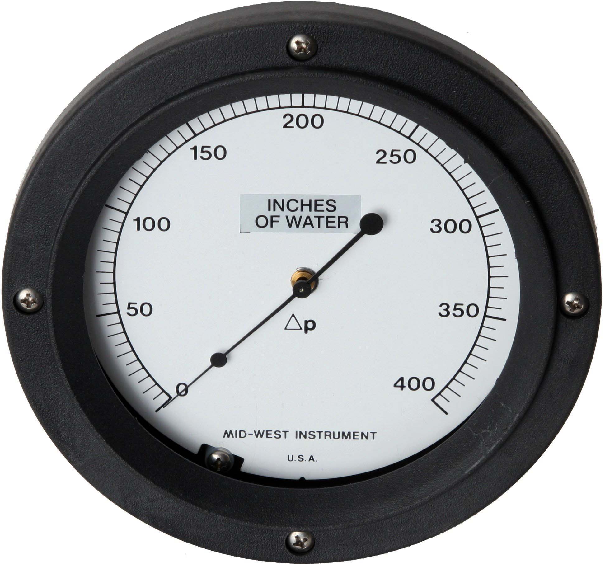
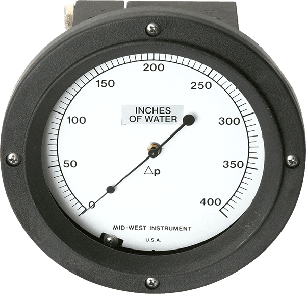
Mid-West® Instrument Model 106 Bellows ΔP Gauge – ± 1/2% or ± 1% Full Scale Accuracy. System pressure is applied to the internal volume of a bellows and mechanical linkage assembly. As pressure changes, the bellows and linkage assembly move to cause an electrical signal to be produced or to cause a gauge pointer to move. The major components of the Model 106 are a two-piece body, bellows sensing element and over-pressure assembly, a torque tube assembly, a range spring and the gauge front assembly.
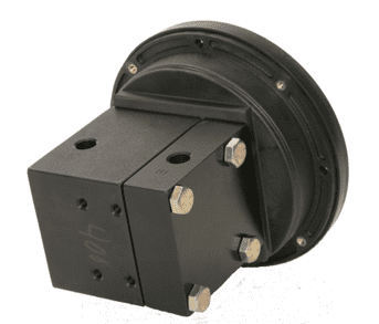
The body halves provide the pressure containment function. They also clamp the sensing element and over-pressure assembly between the halves, isolating the high side and low side pressures of the system. The high side body half also provides a mount for the torque tube assembly and the gauge front assembly.
This assembly incorporates a bidirectional relief valve which provides over-pressure protection in both directions. When over-pressured from the high side, the valve is opened by a mechanical stop as the sensing element deflects to its maximum travel. When over-pressured from the low side, the spring-loaded valve opens when the differential pressure exceeds its maximum rating. The opening of the valve in either direction equalizes the pressure and protects the unit.
Contact Us Today For AvailabilityProduct Features/Benefits
- Rugged Bellows Sensing Element
- Glass Reinforced Thermoplastic Dial case (Panel Mountable)
- Weather Resistant & Corrosion Resistant Gauge Front
- 270° Dial Arc
- Shatter Resistant Lens
- Over-Range Protection, High over Low and Low over High
- Locked-Logic and Micro Switch options
- 5 Year Warranty
- For complete model details See bulletin_105_106.pdf
- Installation and Operation Manual See Bulletin: im105_106.pdf
Specifications / Configuration
- Dial Sizes available: 4-1/2” and 6” Diameters
- Dial Scale Ranges: 0-80” H2O to 0-800” H2O (0-3 PSID to 0-30 PSID)
- Differential Full Scale Ascending Accuracy available: ±1/2% (ASME B40.1 Grade 2A)/±1% (ASME B40.1 Grade 1A)
- Available in a Variety of Dial Scales: Bar, Mbar, kPa, Kg/Cm2, Dual Scale and Square Root for Flow Indication etc.
- Working Pressures up to 6000 PSIG (400 Bar)
- Operating Temp -40°F to +200°F (-40°C to +93°C)
- Weather Protection & Corrosion Resistant
- Material of Construction of Body - Aluminum, Carbon Steel, 316/316L Stainless Steel and Brass (Wetted Part)
- Internal wetted parts-316 Stainless Steel
- Dual Top and Bottom Process connections
- O-rings Materials Buna-N, Viton, and Ethylene Propylene.
- For complete specifications see: Specificationsheet_105-106.pdf
Common Applications
- Pressurized Tank Level Monitoring
- Stationary Tanks – Horizontal or Vertical
- Tanker Transport (For materials such as LOX, CO2, Ammonia, Nitrogen, Helium, Nitrogen, Hydrogen and Argon)
- Water Treatment and Air Conditioning Systems
- Square Root Dials for Direct Reading of Flow Rates
- Pump Performance Monitoring
- Hydraulic Filter Monitoring
- Filter monitoring for Gases
Locked Logic Switch Electrical Specifications – 6” DIAL ONLY
See Bulletin: Electrical Installation and Operation Manual for LLC
“Locked Logic” alarm control is a solid-state optical-electronic control available as an option on Mid-West Models 105 differential pressure gauge. The control is an optical “no-contact” design that does not affect the indicated accuracy of the instrument. The standard unit is designed for an 8 to 28 VDC uninterruptable power input. Optional power inputs include 115 VAC 50-60 hertz, or 220/240 VAC 50-60 hertz. Output interface is via a set of (1) or (2) isolated SPDT or DPDT relay contacts, dependent on the number of set points specified. Visible set pointers are provided, adjustable to within 5% of full scale of each other. Interface to the relay contacts is customer configurable provided the relay contact ratings are not exceeded. An alternate option allows the incorporation of an adjustable dead band. For this configuration the right set pointer determines the upper trigger point, while the left set pointer determines the lower trigger point.
- 1 or 2 Independently adjustable switches with Set Point Feedback
- Requires Input Power to Operate the switches
- SPDT or DPDT Output Options
- Adjustable Deadband option for SPDT or DPDT output (2 set pointers)
- Accuracy of Gauge unaffected by the switch
- Adjustable from 5 to 95% F.S.
- Electrical Enclosures Weather-proof NEMA 4X or NEMA 7
Hazardous Locations:
- Designed for Class I Division I, Groups B, C & D, Class II Division I, Groups E, F and G
Micro-Switch Specifications: 6” DIAL ONLY
See Bulletin: Installation and Operation Manual for Micro-switch
Model 106 can be equipped with one or two independently adjustable SPDT switches which can be set on decreasing or on increasing pressure.
Minimum range requirement for Micro-switch is 80” H2O. The model 106 switch adjust screw and a switch lock screw is accessible after removal of the lens and bezel (removal of 4 screws). Interface to the snap acting micro-switch is via color coded 18 AWG flying leads and a ½” FNPT conduit connection. The assembly does not need power to operate.
- 1 or 2 Independently adjustable switches
- Requires no input power for switches to operate
- SPDT Outputs
- 4 AMP @ 30 VDC
- 3 AMP @ 240 VAC
- 5 AMP @ 120 VAC
- Adjustable from 3% to 90% F.S. on decreasing pressure
- Adjustable from 15% to 95% F.S. on increasing pressure
- CSA Listed – Industrial Control Equipment
Additional Options:
- Pipe Mounting Kit - 2" U-Bolt
- Wall Mounting Kit
- Oxygen Cleaning
- Stainless Steel Tagging
- NACE Certificate (Available for Aluminum and Stainless Steel Bodies only)
- CRN – Canadian Registration Number (1500 PSI Safe Working Pressure Stainless Steel Bodies only)


The Mid-West Advantage
- 5 year warranty
- 30 + Years Hazardous Location product manufacturer.
- OEM and Private Label Capabilities
- Fast on-time Deliveries
- Friendly Customer Support
- Certified Quality System CSA B51-09 SAI GLOBAL
| Model No. | Differential Pressure Range | Accuracy | Working Pressure | Electrical Available | Specifications | Installation/ Operation Manual | Electrical IOM | Drawing |
|---|---|---|---|---|---|---|---|---|
| Model 105 | 0-10" H2O (0-0.4 PSID) to 0-79.9" H2O (0-2.9 PSID) | ±1/2% or 1% Note: 1/2% Full Scale available 30" H2O & above |
Up to 6,000 PSI | LOCKED LOGIC SWITCHES NEMA 4X, Class I Division I, GROUP. B, C & D, Class II Division I, GROUP. E, F & G |
||||
| Model 106 | 0-80" H2O (0-3 PSID) to 0-800" H2O (0-30 PSID) | ±1/2 or ±1% | Up to 6,000 PSI | LOCKED LOGIC SWITCHES NEMA 4X, Class I Division I, GROUP. B, C & D, Class II Division I, GROUP. E, F & G MICRO SWITCHES 0-80" H2O to 0-800" H2O, CSA LISTED IND. CONT. EQUIP. |
||||
| Model 115 | 0-10" H2O to 0-69.9" H2O Tank Level Applications |
±1% | 500 PSI (Optional 1,000 PSI) | None available | N/A | |||
| Model 116 | 0-70" H2O to 0-800" H2O Tank Level Applications |
±1% | 500 PSI (Optional 1,000 PSI) | MICRO SWITCHES 0-80" H2O to 0-800" H2O NEMA 4X, CSA LISTED IND. CONT. EQUIP. |


