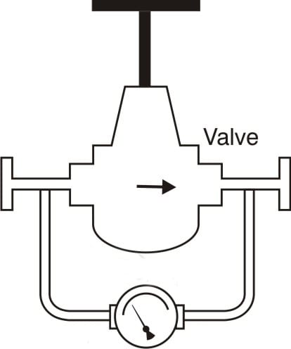
Pipe flow rate control is a crucial aspect of any fluid transport system, as it ensures optimal efficiency and prevents damage to equipment. Valves are commonly used to control flow rate, with the assistance of a differential pressure gauge. Flow rate adjustment is done by adjusting the valves in the pipeline that control an orifice plate, which can be monitored using a differential pressure gauge. Diaphragm type differential pressure instruments are commonly used to control flow rates, with selection based on service and range. These gauges provide accurate and reliable measurements of differential pressure, which can be used to calculate flow rates using the Bernoulli equation.
More Information About Pipe Flow Monitoring
To ensure accurate pipe flow rate measurements, some differential pressure gauges come with glycerin-filled indicators. These indicators limit pointer bounce due to pulsating flow conditions, which can cause inaccuracies in the readings. Proper selection, installation, calibration, and maintenance of differential pressure gauges are essential to ensure accurate and reliable measurements over time. Operators should follow manufacturer’s instructions and industry standards when selecting, installing, calibrating, and maintaining their gauges to ensure that they perform optimally.
By using differential pressure gauges to monitor flow rate monitoring and control, operators can ensure the efficient and safe operation of their fluid transport systems. Flow rate control using valves and differential pressure gauges is a widely used method for optimizing system performance and preventing issues in fluid transport systems. Proper selection, installation, calibration, and maintenance of differential pressure gauges are critical to ensure accurate measurements and precise control of flow rates.