Differential Pressure Instruments (DPI) gauge installation can be a fairly simple procedure, or it can be a frustrating problem. The following are some tips to help eliminate problems and simplify your DPI panel installation.
In most cases instrumentation is generally the last item designed and installed in complex systems. Since this happens frequently, much instrumentation is installed in whatever space is not already occupied. This provides a huge challenge – and at times brilliant solutions – for the instrumentation engineer who is required to put “three pounds in a two pound sack”. For the instrumentation engineer the problem for differential pressure instruments (DPI) is more severe because the DPI has two connections. In addition, the connections must be made so the high pressure connection is made to the high pressure port of the instrument.
DPI configuration variables include port location (end, back, top, and bottom), port type (NPT, BSP, SAE, “O” Ring) and mounting options. (See Figure 1) The DPI supplier should be brought into the program as early as possible so their support people can help the user pick the most cost effective configuration whether it is a standard option or a customized solution. When confronted with these decisions it is important to choose a DPI supplier who can provide a configuration which simplifies the installation process with an existing product or can provide a custom design to solve the problem.
Pre-Planning for DPI Panel Installation
During the design stage every effort should be made to simplify the installation by preplanning the tube and pipe routing. The DPI should be mounted as close to the primary device as possible for best instrument response. For distances less than 50 ft. ¼” tubing or pipe is adequate. For distances from 50 to 100 ft. ½” tubing or pipe is recommended. Instrument lines in excess of 100 ft. should be avoided. Instrument lines should slope a minimum of one inch per foot to avoid liquid or gas entrapment. On gas systems the DPI should be mounted above the primary device so the unit will drain any condensate back into the process line. Conversely, on a liquid system the DPI should be located below the primary device so the unit is self-bleeding. It is recommended that the high side and low side instrument lines do not cross. The number of joints in the instrument lines should be minimized to reduce leak points and improve system reliability. The DPI should not be operated above its’ maximum recommended working temperature. Un-insulated instrument lines will drop the process temperature 50°F (10°C) per foot so an adequate length of tubing must be installed to provide sufficient temperature drop to protect the DPI. If there is vibration in the system, the DPI and instrument lines should be securely mounted to prevent damage. Common mounting options include 2” pipe mounting, panel mounting, and wall mounting and direct mounting. If severe pressure pulsations are present, pulsation dampeners or “snubbers” should installed between the primary device and the DPI in both high side and low side to improve instrument readability and to reduce instrument wear.
Selecting DPI Materials
In addition to choosing the optimum DPI configuration, there are a number of other items to consider. Of utmost importance is to choose DPI materials of construction (pressure containing elements, elastomers and connection configuration) that are suitable for safe use with the system’s pressure, temperature and materials of construction.
Over-Range Protection
DPI has another characteristic that is often overlooked. Many DP units have high working pressures but low differential pressure ranges (i.e. a 5000 psig working pressure with a full scale range of 5 psid).

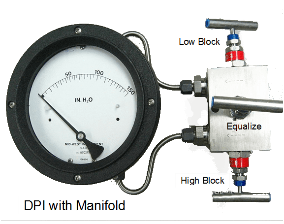
The instrumentation engineer needs to make sure the DPI unit selected has adequate over-range protection. To provide greater margin for error, it is good practice to provide a three valve manifold, or two block valves and an equalizer valve, to allow start-up or shut down without over-pressuring the instrument. Locate all valves or manifolds where they are easily accessible to the operator and label if necessary. (See Figure 2).
Start-Up Tips
The proper practice for start up is to close both block (process) valves and open the equalizer valve prior to start up. Start the system up. When the system stabilizes, gradually open both block valves simultaneously. Close the equalizer valve. The DPI is now on line. To shut down the system, the process is reversed. First open the equalizer valve (your DPI should read zero). Shut down the system. Close the block valves. This procedure is appropriate for use on all DPI.
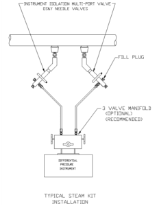
Installation For DPI’s In Steam Systems
Steam systems provide some other unique installation requirements. It is imperative that live steam must not enter the DPI. This is normally accomplished by installing a steam kit or seal
Pot. (See Figure 3) The function of these devices is to allow a column of water to be maintained above the DPI. This water column does not affect the DPI reading but acts as a buffer to keep the steam out of the instrument. This is critical because if steam is allowed to enter the DP instrument, severe damage will result.
Custom Design
Keep in mind that if you run into a DPI panel installation that cannot be easily solved on site, DPI’s can be custom designed to:
- Change port location
- Change mounting holes
- Reverse port back configuration or adding an end connection
These are examples of how your DPI’s can be customized to provide flexibility for the installation process. These are a few common sense tips for trouble free installation of your DPI. Choosing the proper unit to suit the operating parameters of the system while taking into account the best unit from a configuration stand point (connection type, connection locations, and mounting system) can provide an effective and reliable installation.
Mid-West Instrument
Sterling Heights, MI USA
Author: Fred Lueck, President