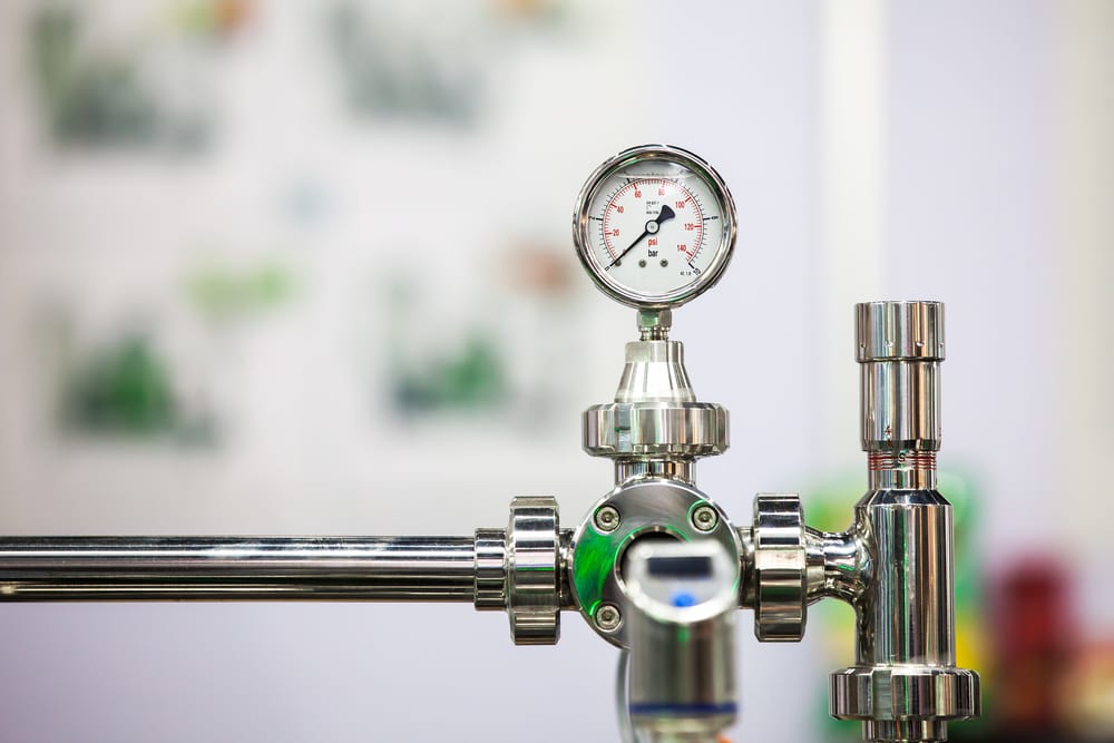
A pressure switch is an integral component in any private well water system. The pressure switch interacts with the water pump that delivers water to your home, telling it when to turn on and off. Wiring a 220 well pressure switch in Michigan requires quality pressure switched, such as those offered by Mid-West Instrument.
Can You Run a Well Pump Without a Pressure Switch?
There are four scenarios in which a well pump can be run without a pressure switch:
- All water output hits the ground (i.e. for an irrigation application), meaning that no pressure setting is required. Instead, a time is usually employed for this type of application.
- You have a relief valve that vents excess flow back into the well. In this case, the presence of bypass flow might be used to stop the well pump. However, if such a system is designed incorrectly, you run the risk of contaminating the well.
- You have an emergency, i.e. a fire, and need all available flow and pressure in one place at one time.
- You have zero cares about tripping the well pump on its thermal overloads, wasting energy, or potentially producing damage at the surface.
How to Install a Pressure Switch
Pressure monitoring is an integral part of many businesses in Michigan. Here’s a step-by-step overview of how Mid-West Instrument’s pressure switch can be installed so that it will ensure accurate monitoring and results.
- Go to the main panel and turn off the power to the pump.
- Test the wiring from the main panel to ensure that the power is off.
- Use the nearest faucet, or a hose bib on the tank tee, drain all water pressure from the system.
- If you are replacing an old switch, remove the switch and its existing wires from the system.
- Secure the new switch to the jet pump or install it on the piping of the existing submersible well pump system. Use Teflon tape on the pressure switch inlet to prevent leaks.
- Using pliers, remove the cover of the new pressure switch and set it aside. A wiring diagram is typically placed inside the cover.
- Loosen the screws on the pressure switch terminal with a screwdriver.
- Feed the wires from the pump motor and the main power supply through the openings on both sides of the switch.
- Attach the pump motor wires to the two terminals in the center, marked “M” or “Load” (T1/T2). Attach the ground wire to the ground screw.
- Attach the power supply from the main breaker to the outside terminals, marked “Line” (L1/L2). Attach the ground wire to the ground screw.
- Reinstall the switch cover and reconnect the power.
- Test the pressure switch for several cycles to ensure that it is working properly.
Call Pressure Switch Professionals You Can Trust in Michigan
For more than 60 years, Mid-West Instrument has been at the forefront of instrument design in the Midwest. Whether you’re looking for a transmitter, gauge, or pressure switch, our innovative team is the one to call. Contact us today and let’s talk further about your application requirements.